
So as luck would have it, I came into possession of two pretty old IoT cameras. Although I had physical ownership of the devices, I was unable to actually use them and was unsure what to do with them. Probably the smartest thing to do at this point would have been to just throw them away and get new cameras that would work better anyways, but in my case, I saw this as a challenge.
Getting Started#
The first step in anything like this was to identify what I actually had and then see if anyone else has already cracked open the cameras. On first inspection, I was able to identify the cameras as ADT OC845 and OC432 models. Looking online I soon stumbled upon some ancient looking blog posts and GitHub repositories that seemed to indicate that these were rather simple to get into.
Easy Part first#
I started with the OC845 because it was a WiFi camera. Rather than go into that just yet, let me tell you what ended up happening with the OC432 camera which is a wired ethernet PoE camera. Long story short, it works exactly like those previous sources say. You put a paperclip into the reset button, hold for a bit, and then plug it into the network (while making sure to block internet access), and then you can login with the username of administrator and no password.
I tell you that because I only discovered that this camera was that easy after I tackled the WiFi model. I was expecting the wired one to be just as hard but was into it in less than ten minutes. It would take me a few weeks to get into the WiFi model.
The Rest of the story#
I tried to no end to get the reset button and default credentials to work on the OC845, but to no end. I was able to hold the WPS button on the back, get it reset, and connect it to my WiFi network without a problem. I could even probe some of the Sercomm-API URLs, but they all required HTTP basic authentcation with credentials that I did not possess. I tried various credentials I found online that should work such as in this blogpost but alas, they also did not work.
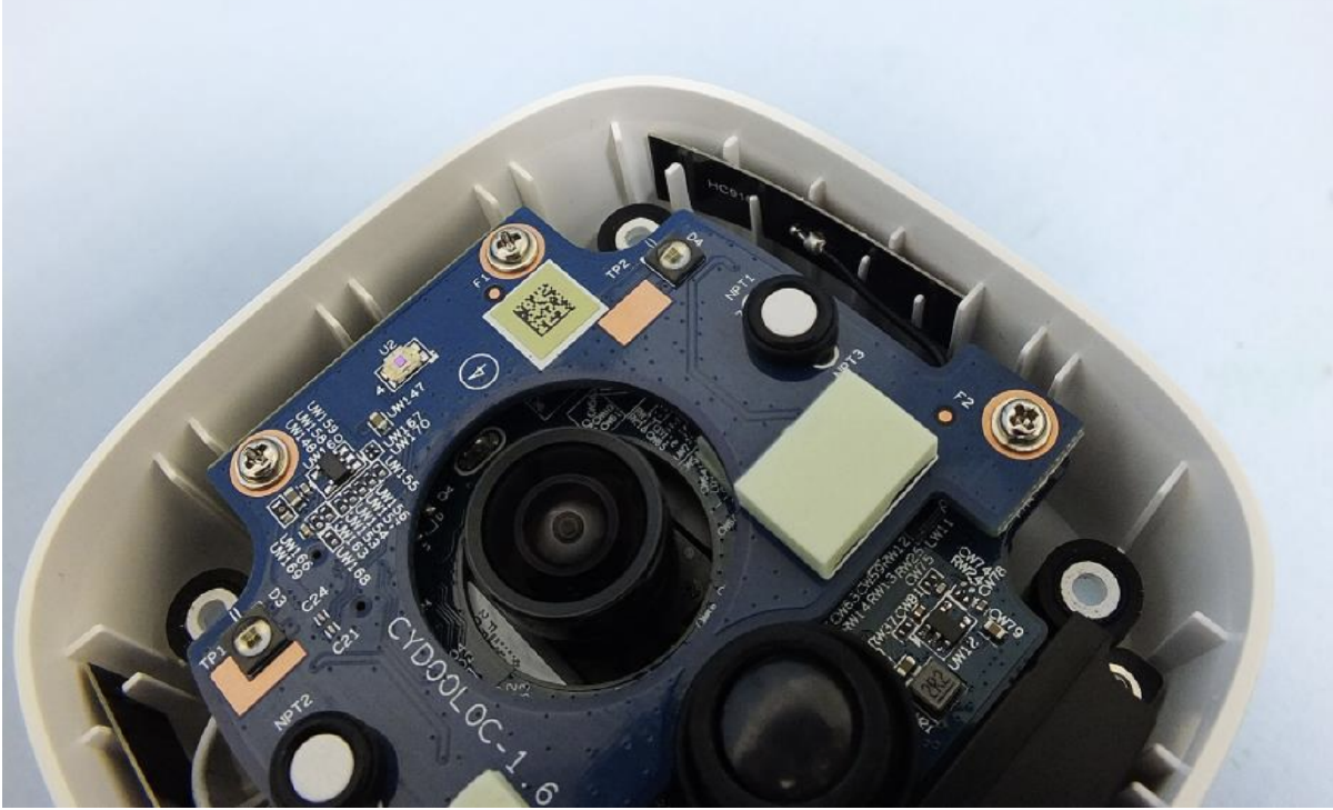
After trying some fairly normal things, I decided to bite the bullet and tear the camera apart to see what lie inside. It was interesting to find just a few PCB boards sandwiched together, but on one I found what appearead to be a UART header as you can see at the top of this photo: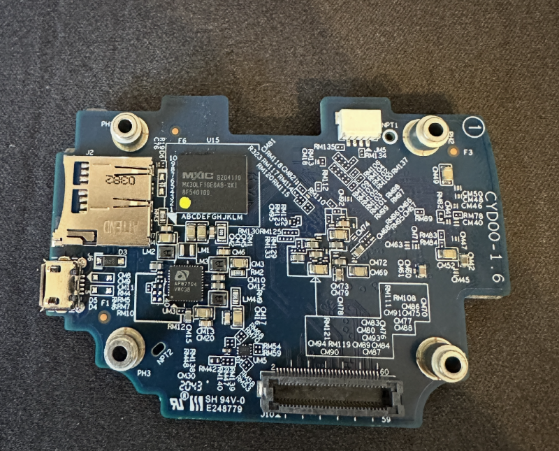
I also discovered this website which happens to have photos of every internal board as well as what the camera looks like put together, and the manual for the camera.
At this point, I was stuck. I didn’t have the connector I needed to make the UART header work, so I had to wait until I could order one. A few days later, I was able to use my new connector socket that I purchased work with my Raspberry Pi Pico that I setup to be a USB to serial converter, and upon booting the camera I was presented with some output in minicom:
NAND: Macronix MX30LF1GE8AB_128MB_PG2K
ret_val of nand read:0
raw magic:FFFFFFFFret_val of nand read:0
raw magic:524F4E47CRC32 of PTB in FW:ED0A4DCA
the correct CRC32:ED0A4DCA
SYS_CONFIG: 0x3007001A POC: 101
Cortex freq: 720000000
ENET freq: 50000000
iDSP freq: 216000000
Dram freq: 528000000
Core freq: 216000000
AHB freq: 108000000
APB freq: 54000000
UART freq: 24000000
SD freq: 50000000
SDIO freq: 50000000
SDXC freq: 60000000

==========================================
Neutral Bootloader  V1.15
==========================================
the model is OC845
other model,do nothing
sc_main(1236):start parse protect area information
load_partition_table(1004):load partition table from flash
*****************Partition table header************
  version 4098
  entry num 6
*****************Partition table entry*************
  id 1 version 4097 offset 0 length 50331648
  id 2 version 4097 offset 50331648 length 50331648
  id 3 version 4097 offset 100663296 length 18874368
  id 6 version 4097 offset 119537664 length 4194304
  id 4 version 4097 offset 123731968 length 9437184
  id 5 version 4097 offset 133169152 length 1048576
**************************************************
At this point, I was getting really excited, and then the boot process completed and I saw the Linux login prompt. Which was a sad sight to see since it meant I needed credentials. I then tried to type into the console, and it didn’t work, go figure.
Needless to say, it took a few days and a purchase of a dedicated serial to USB converter for me to realize that I had swapped the TX and VCC wires (hardware is not my strong suit if you can tell). Once I got input working, I then rushed to try any manner of credentials I had, and they all failed.
Back to the Drawing Board#
Now I was kinda stuck. I had console on the device and the device itself, but I still needed credentials. I finally thought that maybe I could figure out if the password is being generated somehow and if I had an older dump of the firmware, maybe I could figure it out from that.
I found this GitHub issue where someone was looking at a function and claimed to have a password, but it didn’t work. Finally, I found this issue that linked this firmware.
Cool, so now I had some kind of firmware. I used binwalk to extract the firmware and look inside the filesystem, and basically you end up with a few key files:
/etc/rc.sethost
/usr/lib/libcgicomm.so.0.0
/usr/lib/libcgilib.so.0.0
/usr/lib/libsccomm.so.0.0
I fired up Ghidra and started poking around, and low and behold, I found the function from the screenshot in the one GitHub issue:
undefined4 id2pwd(ushort param_1,undefined1 *param_2)

{
  undefined4 local_74;
  undefined1 auStack_68 [16];
  undefined1 auStack_58 [16];
  undefined1 auStack_48 [16];
  undefined1 auStack_38 [16];
  undefined1 auStack_28 [20];

  memcpy(auStack_28,"ABCDEFGHIJABCDEF[SYSTEM]",0x10);
  memcpy(auStack_38,"qrstuvwxyzqrstuvABCDEFGHIJABCDEF[SYSTEM]",0x10);
  memcpy(auStack_48,"0123456789012345qrstuvwxyzqrstuvABCDEFGHIJABCDEF[SYSTEM]",0x10);
  memcpy(auStack_58,"!@#_+!@#_+!@#_+!0123456789012345qrstuvwxyzqrstuvABCDEFGHIJABCDEF[SYSTEM]",0x10)
  ;
  memcpy(auStack_68,
         "0123456789ABCDEF!@#_+!@#_+!@#_+!0123456789012345qrstuvwxyzqrstuvABCDEFGHIJABCDEF[SYSTEM]",
         0x10);
  if (param_2 == (undefined1 *)0x0) {
    local_74 = 0xffffffff;
  }
  else {
    *param_2 = auStack_28[param_1 >> 0xc];
    param_2[1] = auStack_38[param_1 >> 8 & 0xf];
    param_2[2] = auStack_48[param_1 >> 4 & 0xf];
    param_2[3] = auStack_58[param_1 & 0xf];
    param_2[4] = auStack_68[param_1 >> 0xc];
    param_2[5] = auStack_68[param_1 >> 8 & 0xf];
    param_2[6] = auStack_68[param_1 >> 4 & 0xf];
    param_2[7] = auStack_68[param_1 & 0xf];
    param_2[8] = 0;
    local_74 = 0;
  }
  return local_74;
}
And then I used an LLM to re-write it in python for easy use:
def generate_password_from_id(user_id: int) -> str:
    # Corrected character sets based on first 16 bytes
    char_set1 = "ABCDEFGHIJABCDEF"
    char_set2 = "qrstuvwxyzqrstuv"
    char_set3 = "0123456789012345"
    char_set4 = "!@#_+!@#_+!@#_+!"
    char_set5 = "0123456789ABCDEF"

    # Extract 4-bit indices
    index1 = user_id >> 0xc
    index2 = (user_id >> 8) & 0xf
    index3 = (user_id >> 4) & 0xf
    index4 = user_id & 0xf

    # Generate password
    password = (
        char_set1[index1] +
        char_set2[index2] +
        char_set3[index3] +
        char_set4[index4] +
        char_set5[index1] +
        char_set5[index2] +
        char_set5[index3] +
        char_set5[index4]
    )

    return password

# Test
if __name__ == "__main__":
    test_ids = [0x0009, 0x0025, 0x018d, 0x0057, 0xffff]
    for user_id in test_ids:
        password = generate_password_from_id(user_id)
        print(f"User ID: 0x{user_id:04x}, Password: {password}")
And now I was just tring to figure out what the user_id variable value was and then in theory, I would have the password. After staring at the Ghidra decompile for a few minutes it struck me that I wasn’t reading it right and the value being passed to the function was literally the value 0x9. Run that through the Python function and you get Aq0+0009 which is ironically exactly what the “leaked” root password for the device was.
Well, at this point I had the realization that maybe that value was hardcoded in every firmware to a different value, and I could just brute force it, since the maximum value for user_id was only 0xffff and that wouldn’t take too many days to run through a linux console.
I was also feeling kind of burnt at this point, so the thought of letting this go for a few days while still technically making progress was very appealing to me. So I let it start chugging on a modified LLM script that utilzied the previously shown function.
import machine
import time
from machine import Pin

led = Pin("LED", Pin.OUT)

# Configure UART0 (GPIO 0 = TX, GPIO 1 = RX) at 115200 baud
uart = machine.UART(0, 115200, tx=0, rx=1)
uart.init(115200, bits=8, parity=None, stop=1)

# Lists to brute force
usernames = ['root']

def try_login(username, password):
    time.sleep(0.1)
    attempts = 0
    while not uart.any():
        uart.write('\n'.encode())
        time.sleep(0.1)
    line = uart.read().decode('utf-8').strip()
    print(line)
    while 'oc845ffa18d login:' not in line.lower():
        print(line)
        uart.write('\n'.encode())
        time.sleep(0.1)
        while not uart.any():
            time.sleep(0.1)
        line = uart.read().decode('utf-8').strip()
    uart.write((username + '\n').encode())
    time.sleep(0.5)
    while not uart.any():
        time.sleep(0.1)
    line = uart.read().decode('utf-8').strip()
    print(line)
    while 'password:' not in line.lower():
        time.sleep(0.1)
        while not uart.any():
            time.sleep(0.1)
        line = uart.read().decode('utf-8').strip()
        print(line)
    uart.write((password + '\n').encode())
    led.off()
    time.sleep(4)
    led.on()
    while not uart.any():
        time.sleep(0.1)
    response = uart.read().decode('utf-8')
    print("Received response: ")
    print(response)
    print("End attempt")
    if '#' in response or '$' in response or 'sh:' in response:  # Shell prompt indicators
        return True, response
    else:
        return False, response

    return False, "No login prompt found"

# Brute force loop
for username in usernames:
    for id in range(0,0xffff):
        tried = False
        while not tried:
            try:
                password = generate_password_from_id(id)
                success, response = try_login(username, password)
                tried = True
            except Exception as e:
                pass
        print(f"Tried {username}/{password}: {'Success' if success else 'Fail'}")
        if success:
            print(f"Successful login! Response: {response}")
            while True:
                for x in range(0,30):
                    led.on()
                    sleep(.1)
                    led.off()
                print(f"Used {username}/{password}")
I ran it on a Raspberry Pi Pico, and even added the feature to flash the LED on the Pico in a specific way so I could unplug from it and check it later and see whether it found a match. After about three days, it reached the end without finding the password.
Dead End#
By now I was feeling desparate. I started researching anything and everything IoT hacking related to see what I could do short of taking the flash off the chip and reading it (which was a viable, if not difficult option). I started reading about glitch hacking and tried my hand at that, essentially inserting a wire into the NAND flash chip during bootup to cause a short circuit and hopefully corrupt some data being read with the hope that it would drop me at the bootloader or Linux shell.
I was able to successfully glitch and cause data read errors, but unfortunately the developers had done their job and the device just halted after two attempts and didn’t provide me with any access.
Around this time, I also experimented with a Micro USB OTG cable and a USB ethernet adapter to see if that would work and allow me to use the normal reset functionality. I also tried to see if I could get the device itself to become a USB ethernet adapter since it printed some ether gadget things that made it seem possible. None of these things worked and I was left without any options.
A Beacon of Light#
Then I happened to stumble upon this forum post while searching different strings about the processor SOC. And in it, the author describes that to interrupt the Amboot bootloader you just have to hold enter on bootup. I was sitting their thinking its worth a shot at this point. So I booted it up, expecting nothing, but lo and behold it dropped me at the Amboot shell.
I had no clue what Amboot was (and still don’t really), but I was able to figure out a few commands. I could’ve simply used tftp and tried to boot that way, the only issue was that I would’ve needed to figure out how to connect via WiFi from the bootloader menu, which seemed to me like it would be difficult. Luckily, Amboot has a nand command where you can actually dump individual pages of the NAND flash as a hex dump.
So, using my serial to USB and adapting my previous scripts, I wrote a little bit more Python to get me a firmware dump:
import serial
import time

# Serial port configuration
serial_port = '/dev/tty.usbserial-0001'
baud_rate = 115200

ser = serial.Serial(serial_port, baud_rate, timeout=1)

num_of_pages = 65535

def get_shell():
    ser.flush()
    time.sleep(0.1)
    line = ser.readline().decode('utf-8', errors='ignore').strip()
    while 'amboot>' not in line.lower():
        print(line)
        ser.write('\n'.encode())
        time.sleep(0.1)
        line = ser.readline().decode('utf-8', errors='ignore').strip()

def dump_nand_page(id):

    data = bytearray()

    payload = 'nand dump ' + str(id) + '\n'
    ser.write(payload.encode())
    time.sleep(0.01)
    line = ser.readline().decode('utf-8', errors='ignore').strip()
    while 'main data:' not in line.lower():
        time.sleep(0.01)
        line = ser.readline().decode('utf-8', errors='ignore').strip()

    line = ser.readline().decode('utf-8', errors='ignore').strip()
    while 'spare data:' not in line.lower():
        array = line.split(' ')
        for byte in array:
            data += bytearray.fromhex(byte)
        time.sleep(0.01)
        line = ser.readline().decode('utf-8', errors='ignore').strip()

    ser.flush()
    return data


with open('firmware.bin', 'ab') as file:
    get_shell()
    for i in range(0,num_of_pages+1):
        data = dump_nand_page(i)
        file.write(data)

ser.close()
I let that run for a few days, and then I had the firmware, finally!
Home Stretch#
At this point, I thought I knew what to do. I fired up Ghidra, took a look at the same places I had before, and found the same id2pwd function, threw an LLM at it, took the static value of 0x57 and got a password, and tried it, and it didn’t work.
Here is the function in case you happen to need it for some reason (I feel compassionate towards those on random internet blogs reading about obscure IoT cameras now):
def id2pwd(param_1):
    # Initialize the character array (string in Python)
    dictionary = "ABCDEFGHIJABCDEFqrstuvwxyzqrstuv0123456789012345!@#_+!@#_+!@#_+!0123456789ABCDEF"

    passwd = [
        '0',
        '0',
        '0',
        '0',
        '0',
        '0',
        '0',
        '0',
        '0',
    ]

    # Bit manipulations to extract indices
    uVar9 = (param_1 << 0x14) >> 0x1c  # Equivalent to (param_1 << 20) >> 28
    uVar10 = (param_1 << 0x18) >> 0x1c  # Equivalent to (param_1 << 24) >> 28

    # Extract characters from dictionary based on calculated indices
    cVar1 = dictionary[uVar9 + 0x40]
    cVar2 = dictionary[uVar10 + 0x20]
    cVar3 = dictionary[uVar10 + 0x40]
    cVar4 = dictionary[(param_1 & 0xf) + 0x30]
    cVar5 = dictionary[(param_1 & 0xf) + 0x40]
    cVar6 = dictionary[param_1 >> 0xc]
    cVar7 = dictionary[(param_1 >> 0xc) + 0x40]

    # Build the output string in passwd (assumed to be a list or bytearray for mutability)
    passwd[1] = dictionary[uVar9 + 0x10]
    passwd[5] = cVar1
    passwd[2] = cVar2
    passwd[6] = cVar3
    passwd[3] = cVar4
    passwd[7] = cVar5
    passwd[0] = cVar6
    passwd[4] = cVar7
    passwd[8] = '\0'  # Null-terminate the string

    passwd_str = ""
    for char in passwd:
        passwd_str += char

    return passwd_str

print(id2pwd(0x57))
The key difference with the firmware of this camera is that ADT added their own stuff on top of the original Sercomm firmware. So going through Ghidra I was able to eventually find the specific binary being called and start to work through that, eventually finding the following function:
generatePasswordFromMAC(char *mac,size_t maclen)
{
  int iVar1;
  size_t sVar2;
  size_t __n;
  size_t maclen_local;
  char *mac_local;
  uchar obuf [20];
  uchar[0] *ibuf;
  int i;

  maclen_local = maclen;
  mac_local = mac;
  adcStrupper(mac);
  __n = maclen_local + 0x21;
  iVar1 = -(maclen_local + 0x28 & 0xfffffff8);
  memset((void *)((int)&maclen_local + iVar1),0,__n);
  strncpy((char *)((int)&maclen_local + iVar1),mac_local,__n);
  sVar2 = strlen((char *)((int)&maclen_local + iVar1));
  strncat((char *)((int)&maclen_local + iVar1),"06D58FFA826502BA52D3317A95169346",(__n - sVar2) - 1)
  ;
  obuf[0] = '\0';
  obuf[1] = '\0';
  obuf[2] = '\0';
  obuf[3] = '\0';
  obuf[4] = '\0';
  obuf[5] = '\0';
  obuf[6] = '\0';
  obuf[7] = '\0';
  obuf[8] = '\0';
  obuf[9] = '\0';
  obuf[10] = '\0';
  obuf[0xb] = '\0';
  obuf[0xc] = '\0';
  obuf[0xd] = '\0';
  obuf[0xe] = '\0';
  obuf[0xf] = '\0';
  obuf[0x10] = '\0';
  obuf[0x11] = '\0';
  obuf[0x12] = '\0';
  obuf[0x13] = '\0';
  sVar2 = strlen((char *)((int)&maclen_local + iVar1));
  SHA1((uchar *)((int)&maclen_local + iVar1),sVar2,obuf);
  for (i = 0; i < 6; i = i + 1) {
    printf("%02x",(uint)obuf[i]);
  }
  return;
}
Using the power of LLMs, I was able to convert to Python and get:
import hashlib

def generatePasswordFromMAC(mac, maclen):
    # Convert mac string to uppercase (equivalent to adcStrupper)
    mac = mac.upper()

    # Calculate buffer size and alignment
    __n = maclen + 0x21
    iVar1 = -(maclen + 0x28 & 0xfffffff8)  # Align to 8-byte boundary

    # Create a bytearray for string operations (simulating C's memory buffer)
    buffer = bytearray(__n)
    buffer[:maclen] = mac.encode()  # Copy mac into buffer

    # Append the constant string
    constant = "06D58FFA826502BA52D3317A95169346"
    buffer[maclen:maclen + len(constant)] = constant.encode()

    # Compute SHA-1 hash of the buffer
    obuf = hashlib.sha1(buffer[:maclen + len(constant)]).digest()

    # Print first 6 bytes of the hash in hexadecimal
    for i in range(6):
        print(f"{obuf[i]:02x}", end="")

    return

mac = "0a0a0a0a0a0a"
generatePasswordFromMAC(mac, len(mac))
And then I tried the password, and it worked! I had root on the device and was able to do as I pleased with it.
Fortunately, the root password also worked to get into the web interface of the device with the username administrator and I was able to change the password, disable the VPN that was attempting to call back to ADT, and setup RTSP video feeds.
Conclusion#
So all in, I probably spent a month on and off working on this, but I was happy to have access to both cameras. I learned a lot from the experience, and it was fun to muck around in weird Linux setups and see the weirdness that is older IoT code. Feel free to leave a comment if you had any questions or if you want a copy of the firmware for further research.
References#
- https://shkspr.mobi/blog/2013/11/hacking-around-with-network-cameras/
- https://shkspr.mobi/blog/2017/11/telnet-and-root-on-the-sercomm-icamera2/
- https://github.com/edent/Sercomm-API
- https://web.archive.org/web/20230123041046/https://dl.packetstormsecurity.net/papers/general/reverse_engineering_ip_camera_firmware.pdf
- https://itbyfire.blogspot.com/search/label/xfinity%20camera%20hack%20icamera2%20hacking%20home%20security
- https://fccid.io/P27OC845/User-Manual/Users-Manual-4489631
- https://www.ispyconnect.com/camera/adt
- https://www.manualslib.com/manual/1885455/Adt-Oc845.html?page=6#manual
- https://www.reddit.com/r/homesecurity/comments/14qv04q/oc845_adt_default_userpass/
- https://www.reddit.com/r/videosurveillance/comments/ca6u1w/working_with_proprietary_cameras_ie_comcast_and/
- https://community.home-assistant.io/t/use-for-that-old-adt-camera/390634
- https://riverloopsecurity.com/blog/2020/01/hw-101-uart/
- https://iridiumxor.wordpress.com/2019/04/09/trouble-for-nothing/
- https://gist.github.com/ThomasKaiser/d99228ac986378c41f4f8e6bc3f5cb70
- https://en.wikipedia.org/wiki/ARM_Cortex-A9
- https://dashcamtalk.com/forum/threads/mini0801-hacking-hardware-and-software.3157/
- https://github.com/santeri3700/opticam_o8_hacking
- https://github.com/hello/kasa/blob/master/ambarella/amboot/include/amboot.h
- https://github.com/hello/kasa/tree/master
- https://ipcamtalk.com/threads/unbricking-another-mini-ptz-v2-skipping-much-of-the-tech-stuff.12929/
- https://dc.str2b.dev/ambarella/firmware
- https://www.infosecinstitute.com/resources/penetration-testing/gaining-shell-access-via-uart-interface-part-3/
- https://gist.github.com/pepe2k/d1467195abdffbcf2615e066fd9d42b7
- https://github.com/digiampietro/hacking-gemtek?tab=readme-ov-file#splitting-the-eeprom-image-partitions